.webp?width=91&height=70&name=MCDLG%20Logo%20(Resize).webp)
In this article, we review AMCA's test standards for measuring pressure drop for control dampers, including across multiple installation types. Learn how these tests determine a damper's air performance with the MCDLG Newsstand.
Control Dampers in HVAC
Control dampers direct airflow through your HVAC system. There are two important traits that define a control damper’s effectiveness: the damper’s ability to close tightly and its ability to pass air through open blades with minimal resistance. These traits are air leakage and air performance. In the HVAC industry, both traits are measured to standards created by the Air Movement and Control Association, or AMCA. Let's look at how AMCA-approved tests measure a control damper’s air performance.
As we explain in "Balanced Flow", all HVAC equipment in your ductwork will cause a certain amount of static pressure. Static pressure will resist the dynamic pressure of airflow as it passes through the control damper, which creates a pressure differential that lowers the airflow’s dynamic pressure. This difference in pressure is commonly known as “pressure drop”. A lower pressure drop means less restricted air flow and more efficient air performance across the HVAC system. AMCA testing measures pressure drop to determine the air performance of louvers and control dampers.
Starting a new project? Contact Air Balance about our line of control dampers. Let's work together to meet your requirements!
AMCA - The Air Movement and Control Association
What is AMCA? AMCA is the Air Movement and Control Association, an international not-for-profit association of manufacturers who set standards and test protocols for air system components including air fans, air flow measurement tools, louvers, dampers, and other HVAC parts. AMCA establishes reliable standards for the HVAC industry. AMCA test protocols include water penetration and wind driven rain testing for louvers, and air performance testing for louvers and HVAC control dampers.
When a product completes testing in accordance with AMCA's test protocols, the product receives an AMCA CRP seal. AMCA CRP seals can represent a single test, such as the air performance seal, or they can represent multiple tests. For example, one seal can display ratings for air performance, wind driven rain, and water penetration. The seal will be displayed on the manufactured product and on the product’s data sheet. AMCA rating seals signify that all test data was reliably measured and collected in accordance with AMCA’s standards.
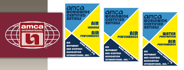
An AMCA seal can list multiple ratings at once. Control dampers are typically rated for air performance and air leakage.
For air performance, control dampers will undergo AMCA’s tests for determining pressure drop in accordance with AMCA Standard 500-D. Once testing is complete, the damper receives an AMCA Rating seal for Air Performance. These tests measure the pressure drop caused by the damper with its blade in the full-open position.
Testing for Air Performance
There are three configurations for the air performance test. Each configuration is designed to simulate a real-world application for control dampers.
Figure 5.2 – The test damper is fixed to one end of a test duct, with its back pointed towards the opening of the duct. Test fans are located at the opposite end of the test duct, to pass air through the face of the damper and out of the test duct. This configuration simulates a control damper tied to an exhaust point in the HVAC system. These dampers will open to release air from the duct.
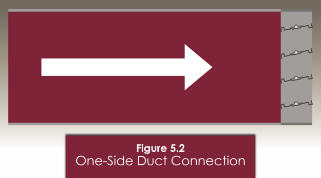
Pictured: The test configuration for Figure 5.2. The damper is connected to one end of a duct.
Figure 5.3 – The test damper is installed between lengths of ductwork, so that both ends are connected to ductwork. Test fans will be located opposite the damper’s face, so that air will flow through the face side of the damper during the test. This configuration simulates the most common installation for control dampers. These dampers open and close to regulate airflow through the system.
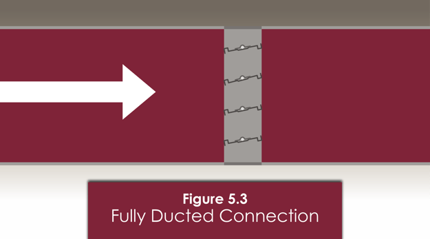
Pictured: Figure 5.3 is the most common installation for a damper. The damper is connected to ducts on both sides.
Figure 5.5 – The test damper is installed onto an over-sized duct chamber with a plenum mount. The oversized duct will end with a smaller opening, where the damper will be installed. The plenum mount places the damper over the opening, so that only the blades of the damper are exposed to the airstream. This configuration produces a different airflow environment than Figure 5.2, but both test figures are designed to simulate an exhaust damper expelling air from the duct, into an open space.
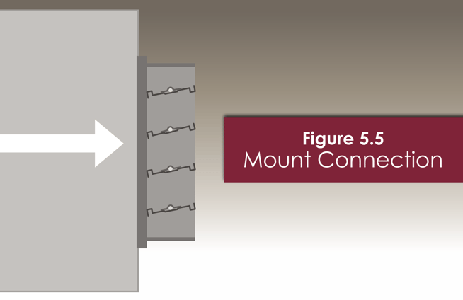
Pictured: The test configuration for Figure 5.5, a plenum-mounted damper. The damper is mounted onto the opening, instead of inside it.
For all configurations, a fan system will run air through the duct. Air measuring instruments are placed near the damper to measure the changes in pressure as air passes through the open damper. This pressure differential is recorded as the damper’s pressure drop at the tested air velocity.
Technicians will increase the fan speed as the test progresses to measure pressure drop at higher air velocities. Pressure drop increases with air velocity and can decrease with greater free area between damper blades. Therefore, control dampers must complete air performance tests at multiple air velocities across test dampers of varied sizes. These data points give an accurate picture of how the damper will affect airflow when fully open.
The Data for Air Performance
Air performance data is plotted on a line graph. The static pressure drop is typically listed on the Y-axis and the damper's face velocity will move along the X-axis. As face velocity increases, the static pressure drop will also increase. This creates a straight line that trends upward as it progresses across the X-axis. Static pressure and air velocity are corrected to a standard air density of 0.075 ft/lb³. This correction standardizes the pressure drop data for all AMCA-rated control dampers.
The pressure drop graph will list the pressure drop of a louver or damper at various face velocities. Control dampers will have multiple lines on the graph that indicate the various damper sizes examined during the test, while louvers will only have one line for one test size.
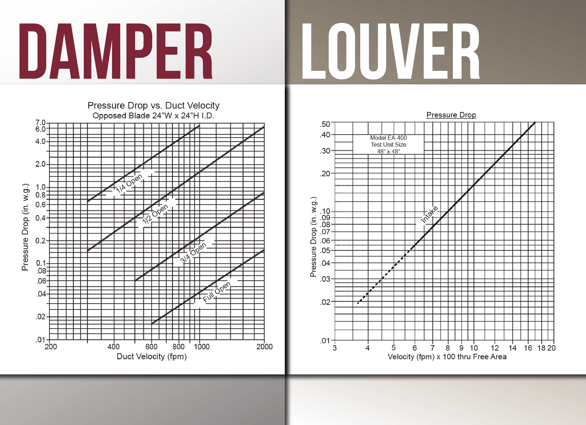
To determine pressure drop for a potential damper:
- Determine the size of the damper and the required air velocity of the duct section receiving the damper.
- If multiple lines are present, find the line that matches the potential damper
- Follow the line across the graph to the required air velocity
- The line will intersect at a specific amount of pressure drop. This will be the amount of pressure drop caused by the damper at the specified air velocity.
Control dampers that complete these tests will receive an AMCA Rating seal for Air Performance. The rating seal is not indicative of a damper’s performance; it signifies test completion and test data verification. AMCA seals convey that the HVAC equipment completed the tests listed on the rating seal and that all test data was collected according to AMCA standards. All AMCA tests and data collection are performed in accordance with AMCA’s testing standards in an AMCA-accredited laboratory.
You can rely on the pressure drop data listed on a control damper’s submittal when you see the AMCA CRP seal for Air Performance. It's important! An efficient HVAC system will pass air from point to point with the least amount of pressure drop. Looking for more on efficiency? Read our quick Condenser article on air performance for a few pointer on choosing louvers and dampers for better HVAC efficiency.
For more on control dampers, check out these Newsstand articles:
Air performance is a key consideration when choosing control dampers. Can you think of anything else that might be important? What else do you consider when choosing control dampers for a project? Tell us in the Comments section. We want to hear from you!
MCDLG is Here to Help!
Need some help? Maybe you have a specific question about a current job? Or do you need a head start on your next project? Talk to MCDLG! We can bring our 50+ years of experience to the table. We are here to help you.

From continuing education to equipment considerations, all the way to providing top-quality finished products, and to post-sales support. We assist our customers every step of the way. Interested? Read our article on all the ways we can help you: MCDLG is Here to Help!
Need help right away? Contact MCDLG today. We are ready to help you.