In this article, we review important terms for selecting louvers and dampers. We will go over what they mean in HVAC and why they are important to building an efficient HVAC system!
Important Terms in HVAC Design
Louvers and dampers seem like simple devices, but there are a lot of things to consider. And you will need to understand certain technical terms to make the best decisions.
The key to building an HVAC system is finding the balance between airflow, energy use, and requirements: get air through the system with the least amount of energy, while meeting the building's requirements.
This balance starts by understanding the important terms involved in choosing louvers and dampers.
Starting a new HVAC project? Looking for dampers? Consider adding the 517-518 control damper from Arrow United Industries. Let's work together on your next project.
Free Area
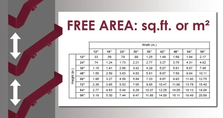
Free area refers to the amount of open space between the blades of a louver or damper. More free area typically means better air performance.
However, certain blade features will reduce the free area of the damper or louver, such as drainable channels and catches. You can measure free area in square feet or meters, or as a percentage of the louver's total area.
For adjustable louvers and dampers, measure the free area with the blades rotated to the fully open position. Free area will increase with the size of the louver or damper.
Pressure Drop
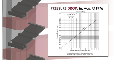
Pressure drop is the loss of pressure and velocity as air moves across a louver or damper, measured in inches of water gauge at an air velocity in feet per minute (in. w.g. @ FPM). With louvers and dampers, this refers to the drop in pressure as air passes through the free area between open blades.
All louvers and dampers will cause pressure drop. Read our quick condenser article on air performance for louvers and HVAC dampers. Here are a few pointers:
- Search for equipment with the least pressure drop that still meets the application's requirements, such as severe weather protection.
- Louvers with blade catches and drain channels will incur more pressure drop than flat, featureless blades. The same is true of control damper blades.
- Experts consider lower pressure drop better for air performance.
For more information on louvers and dampers, check out these articles on the MCDLG Newsstand:
- Louvers by the Numbers
- Five Types of Dampers and when to use them
- Three Common Types of Louvers
Beginning Point of Water Penetration
Exclusive to louvers
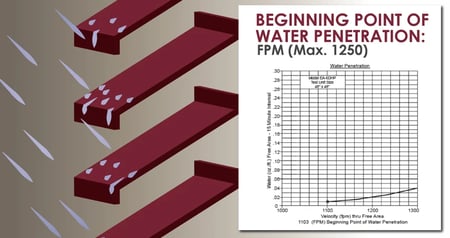
The beginning point of water penetration is the point, measured in air velocity, when water will infiltrate a louver. We often shorten this term to "water penetration". Although most louvers protect the opening from light rain, manufacturers build some louvers specifically to prevent water infiltration.
The key to protecting an opening is finding louvers with a higher beginning point of water penetration than its desired face velocity.
Louvers with a high beginning point of water penetration can intake greater air velocities and maintain their protection against rainfall. AMCA-approved laboratories measure the beginning point of water penetration by simulating light rainfall.
These tests follow AMCA Standard 500-L. We plot the test data on a curved line graph and present it on the louver submittal.
A higher beginning point of water penetration will provide a greater level of protection. Read how AMCA-approved laboratories perform these tests with our Newsstand article: AMCA Testing - Water Penetration. Manufacturers design severe weather louvers to prevent water penetration at higher air velocities. The industry typically refers to these as wind-driven rain louvers.
Wind Driven Rain
Exclusive to louvers
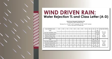
Wind driven rain refers to a louver's ability to reject rainfall during a severe weather event. In wind driven rain testing, testers measure the water rejected by the louver’s blades at a predetermined air velocity under simulated severe weather.
These tests follow AMCA Standard 500-L for wind driven rain testing. Read more about wind driven rain testing on the MCDLG Newsstand.
We typically list metrics for wind-driven rain tests at various airflow rates, and each data point includes a percentage of test water rejection and a letter rating: Class A ratings are best, rejecting 99% or more simulated rainfall during testing. To understand a louver's capabilities, review the wind driven rain data listed on the louver's submittal.
Static Pressure
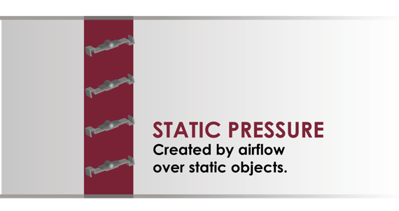
Static pressure is the pressure created as air flows across or through objects in an airstream. This creates a pressure differential from one side of the object to the other. All louvers and dampers will cause a certain amount of static pressure, even with their blades in the fully open position.
Static pressure will increase as more air flows through, and excessive static pressure can make it difficult to pass air through an HVAC system. It is important to minimize static pressure where possible to minimize the resistance to airflow.
Dynamic Pressure
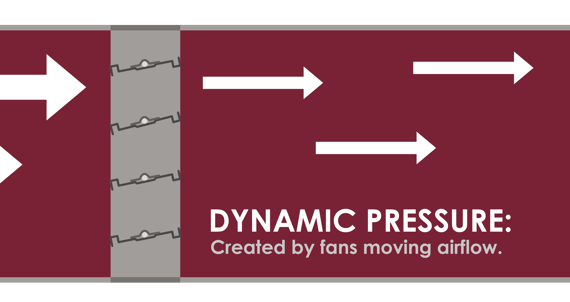
Dynamic pressure is the pressure exerted to move air. For an HVAC system, fans will create the dynamic pressure required to drive air through the ductwork.
Dynamic pressure must exceed the static pressure in the duct for air to move through. In "Balanced Flow", we discuss the relationship between static and dynamic pressures, and how to minimize pressure drop in your system.
Efficient HVAC systems can maintain adequate dynamic pressure using the least amount of power possible. This is the key to maintaining an energy efficient and cost-effective HVAC system.
Max Static Pressure
The maximum static pressure a damper can safely operate with in a duct. The damper will create static pressure, and this pressure will increase as the airflow rate increases. Every damper will have a maximum rated static pressure. Exceeding the damper's static pressure limit prevents it from reliably opening or closing.
Even if the damper works in these conditions, you risk damaging the damper’s components. Review the project's specifications to ensure your dampers will operate safely in their ducts.
Duct Velocity
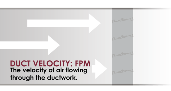
Duct velocity is the velocity of air flowing through a duct, typically measured in feet per minute (FPM).
Your project will have different velocity requirements for different ducts, depending on where they are in the system and their intended purpose. Increase the speed of the system’s fans to increase duct velocity. However, excessive static pressure will make it difficult to achieve the desired duct velocity.
Keep ducts clear of unnecessary obstructions, so that increases in duct velocity will require less power. Make sure the dampers in your duct can operate by comparing the duct’s velocity with the damper’s max face velocity.
Face Velocity
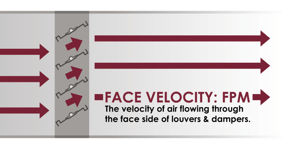
The velocity of air flow as it passes into the front side of a louver or damper, measured in FPM. Air flow will generate pressure drop as it passes through free area, which affects air velocity.
The face velocity of the louver or damper will help you determine its potential pressure drop. You should also make sure the louver’s face velocity will not exceed its beginning point of water penetration. This will ensure the louver works for your building and protects the opening from rain infiltration.
Max Velocity
The maximum air velocity allowed for safe damper operation. The damper’s max velocity refers to face velocity, or the velocity of air passing through the face of the damper. Exceeding this face velocity limit prevents the damper from reliably opening or closing.
Consult the specifications documents for your building project. With these, you can determine the duct velocity of the surrounding ductwork to gauge what you will need for the max velocity of the damper.
Air Leakage
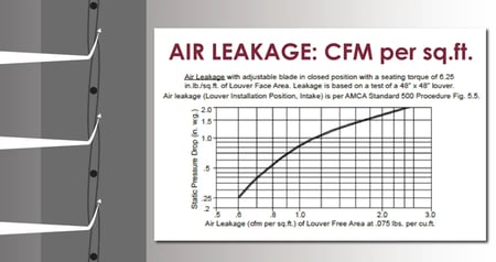
Air leakage is the amount of air that passes through the blades of a closed adjustable louver or damper at a specific air velocity. No louver or damper will be airtight, but even a small amount of leakage can create problems when driving air through the system.
Testers measure air leakage in louvers and airflow dampers through testing performed according to AMCA Standard 500-L (louvers) and AMCA Standard 500-D (dampers). Choose adjustable louvers and dampers with tight closure to maximize air performance.
Learn more about air leakage and how it can kill air performance with our Newsstand article: Air Leakage - The Performance Killer
Leakage Class
For Life Safety dampers
For life safety dampers, leakage refers specifically to smoke passing through a closed smoke or combination fire-smoke damper.
No damper is truly air tight, but it is important to contain smoke and noxious fumes during a fire event. Testing facilities test life safety dampers under UL standards. These enhanced testing methods measure smoke infiltration during a fire event.
The amount of leakage allowed will determine the leakage classification of life safety dampers; Leakage Class I is best because it allows the least amount of smoke to pass. One can rate a damper for both leakage types: AMCA's air leakage rating and UL's smoke leakage classification. Smoke and fire-smoke dampers will require UL's leakage class.
Static & Dynamic Closure
For Life Safety dampers
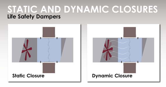
For life safety dampers, the words “static” and “dynamic” refer to the damper’s closure type. Static dampers will only close if there is no air flowing through the duct. Dynamic dampers close against airflow.
Whether system fans will shut down, remain running when an alarm is tripped, or restart as part of a smoke control system will determine the type of damper. Smoke dampers and combination fire-smoke dampers require dynamic closure, so they can close at the first signs of smoke and regardless of the fan system.
Are there any terms we missed? Is there anything in your specs that you don't understand? Tell us in the Comments section. We are here to help!
Starting a new project? Arrow United Industries can help you find the right airflow dampers! Check out our 517 - 518 airfoil control damper, built for air performance.
Need help right away? Contact MCDLG today. We are ready to help you.
.webp?width=91&height=70&name=MCDLG%20Logo%20(Resize).webp)
.webp)


